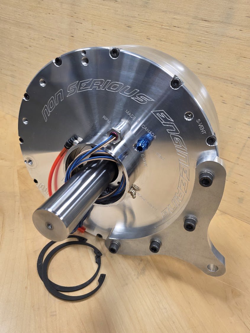
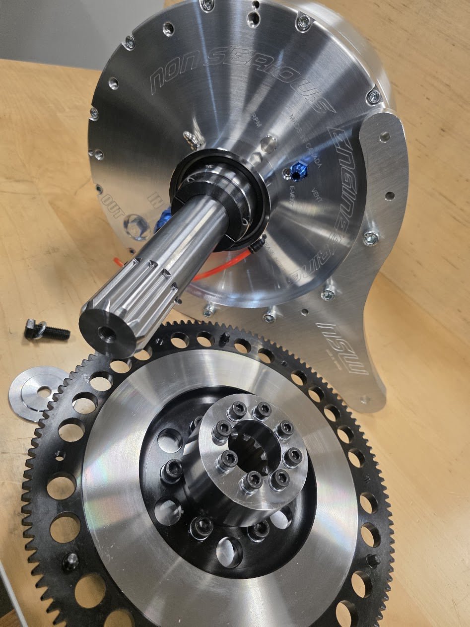
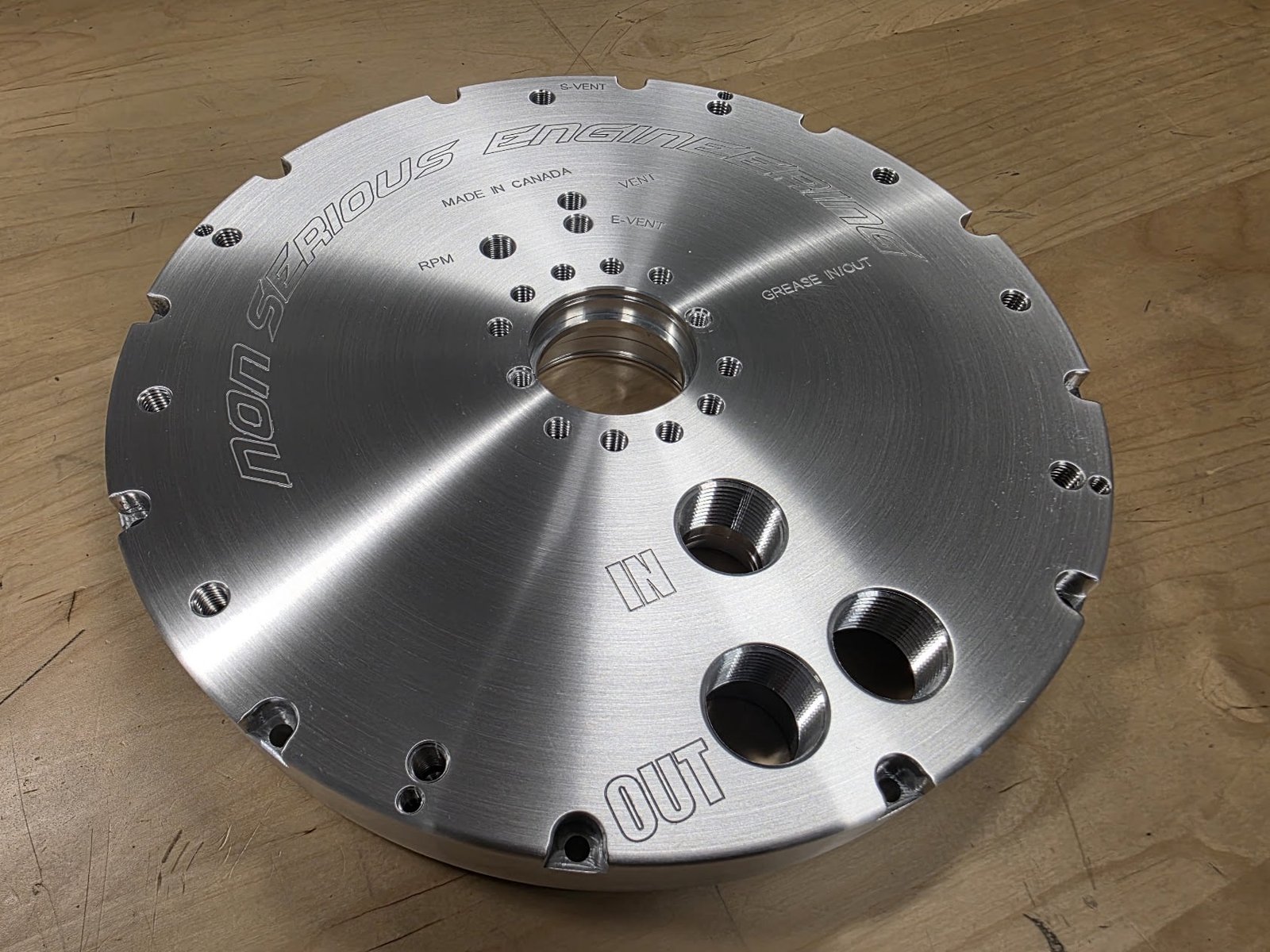
Water Brakes 


Mobirise Website Builder
3in Single Rotor 

Tune your engine

Mobirise Website Builder
5in Single Rotor 

Tune your engine

Mobirise Website Builder
7in Single Rotor 

Tune your engine

Mobirise Website Builder
9in Single Rotor 

Tune your engine

Mobirise Website Builder
9in Dual Rotor 

Tune your engine

Mobirise Website Builder
11in Single Rotor 

Tune your engine

Mobirise Website Builder
13in Single Rotor 

Tune your engine

Mobirise Website Builder
13in Dual Rotor 

Tune your engine

Mobirise Website Builder
19in Single Rotor 

Tune your engine

Mobirise Website Builder
19in Dual Rotor 

Tune your engine

Mobirise Website Builder

NSW Water-Brake Dynamometers

Simple, Powerful and Proven Engine Load Technology

A water-brake dynamometer is one of the most effective methods of absorbing and measuring engine power.

From small motorcycle and kart engines to high-output automotive, diesel, marine and industrial engines, the same fundamental principle can be scaled to absorb enormous amounts of torque and horsepower.

NSW water-brake absorbers are designed around this principle with a range of brake diameters, rotor configurations and bearing arrangements to suit different engine speeds and power levels.

NSW water-brakes are available from 3-inch through 19-inch, with single-rotor and dual-rotor configurations available depending on the application.

How Does a Water-Brake Dynamometer Work?

Unlike a friction brake, a water brake does not rely on brake pads or mechanical friction to absorb engine power.

Instead, it uses water and momentum transfer.

The engine is mechanically connected to the water-brake shaft. As the engine rotates the shaft, the rotor inside the absorber rotates between stationary stator surfaces.

Both the rotor and stator contain specially designed pockets or cavities.

Water is introduced toward the inner region of the absorber. The rotating rotor captures and accelerates the water outward.

The water is then directed into the stationary stator pockets, where its velocity and direction are changed.

It is then redirected toward the rotor.

This creates a continuous cycle:

Rotor → Water Acceleration → Stator → Water Redirection → Rotor

Thousands of these interactions occur every minute.

Changing the momentum of the water requires energy.

That energy comes directly from the engine.

The result is a powerful hydraulic resistance acting against the engine.

Where Does the Engine Horsepower Go?

A water brake is an absorption dynamometer.

The horsepower produced by the engine must therefore be absorbed somewhere.

Inside a water brake, mechanical energy from the engine is transferred into the circulating water and ultimately becomes heat.

The heated water exits the absorber and is replaced with cooler incoming water.

This means the water performs two jobs simultaneously:

1. It creates the braking load.

2. It carries the absorbed engine energy away as heat.

This is one reason water brakes can be extremely compact relative to the amount of power they can absorb.

Rotor and Stator Pocket Design

The heart of a water brake is not simply the rotor diameter.

The geometry of the rotor and stator pockets has a major influence on how the absorber behaves.

Pocket characteristics can include:

pocket depth
pocket width
pocket count
radial position
vane geometry
pocket volume
rotor-to-stator relationship
water entry and discharge characteristics

These features influence how quickly water is accelerated, redirected and exchanged between the rotor and stator.

Different geometry can therefore produce very different torque characteristics from absorbers of similar overall dimensions.

A brake intended for a high-torque, relatively low-RPM engine does not necessarily require the same internal geometry as a brake designed for a small engine operating at extremely high RPM.

This is why NSW develops water-brake sizes and rotor configurations around the intended torque, horsepower and RPM operating range, rather than treating diameter alone as the rating of an absorber.

Why Rotor Diameter Matters

Water-brake torque capacity increases dramatically as absorber diameter increases.

A commonly referenced relationship for hydrokinetic brakes is:

T = k × N² × D⁵

Where:

T = absorbed torque
N = rotational speed
D = rotor diameter
k = a coefficient influenced by the internal hydraulic geometry and operating conditions

The important part is the relationship with diameter.

Diameter is raised to the fifth power.

This demonstrates why increasing rotor diameter can dramatically increase the potential torque absorption of a water brake.

It also explains why NSW offers multiple absorber sizes instead of attempting to make one water brake cover every engine application.

Single-Rotor vs. Dual-Rotor Water Brakes

NSW water brakes can use different rotor arrangements depending on the required capacity.

Single Rotor

A single-rotor absorber provides a compact package suitable for applications where the required torque and horsepower fall within the operating envelope of that brake.

Advantages can include:

compact dimensions
lower rotating mass
simple installation
excellent power absorption for its size
suitability for many engine-development applications
Dual Rotor

A dual-rotor configuration increases the available hydraulic interaction area and absorption capability.

This makes dual-rotor designs particularly useful where substantially greater torque or horsepower must be controlled without simply increasing rotor diameter.

They are suited to applications ranging from high-performance automotive engines to large diesel, marine and industrial powerplants.

How Torque Is Actually Measured

One important point about dynamometers is often misunderstood:

The dynamometer directly measures torque. Horsepower is calculated from torque and RPM.

When the engine turns the water-brake rotor, the hydraulic reaction attempts to rotate the absorber housing in the same direction.

The housing is restrained by a torque arm connected to a load cell.

The load cell measures this reaction force.

Because the torque-arm length is known:

Torque = Force × Distance

Once engine speed is measured by the RPM sensor, horsepower can be calculated.

For horsepower and torque expressed in imperial units:

HP = Torque (lb-ft) × RPM ÷ 5252

For example, an engine producing:

500 lb-ft at 6,000 RPM

produces approximately:

571 HP

The water brake provides the load.
The load cell measures the reaction force.
The RPM sensor measures rotational speed.
The data-acquisition system calculates and records the results.

Controlling Engine Load

The amount of water participating inside the absorber determines how aggressively the brake loads the engine.

Generally:

More effective water volume = More Load

Less effective water volume = Less Load

Water flow can be controlled manually or through an electronically controlled load valve.

With an automated control system, the dyno controller can continually adjust the valve to maintain or change the desired engine operating condition.

This allows testing such as:

RPM sweeps
steady-state testing
engine break-in
ignition tuning
fuel tuning
turbocharger testing
boost-control development
cooling-system evaluation
endurance testing
power and torque measurement

The water brake therefore does much more than produce a peak horsepower number.

It allows the operator to control the operating condition of the engine while measuring its response.

Water Supply Is Part of the Dynamometer

A high-performance water brake requires a properly designed water system.

The absorber cannot perform correctly if the water supply cannot maintain adequate flow and stable pressure.

As engine power increases, the system must move enough water both to create the required hydraulic loading and to carry away the heat generated during absorption.

A typical installation may include:

Water Reservoir → Pump → Pressure Regulation → Load-Control Valve → NSW Water Brake → Discharge / Cooling System

Depending on power level and installation, discharged water may be sent to waste or returned through a cooling system and reservoir for recirculation.

Stable supply pressure is particularly important for repeatable load control. Fluctuating supply pressure can cause the amount of water inside the absorber to change and therefore cause unstable engine loading.

Why Water Brakes Are Excellent for High-Power Engine Testing

Water brakes have been used for engine development for generations for a simple reason:

The technology works.

A properly sized water brake provides extremely high power absorption in a relatively compact mechanical package.

Advantages include:

very high horsepower capability
very high torque capability
compact absorber size
comparatively low mechanical complexity
excellent steady-state loading
scalable design
straightforward torque measurement
effective heat removal through the working water
suitability for gasoline, diesel, rotary, motorcycle, marine and industrial engines

There are no friction pads attempting to absorb thousands of horsepower.

The engine's energy is transferred hydraulically into the water and carried away as heat.

NSW Water-Brake Range

NSW develops water-brake absorbers for applications ranging from small high-RPM engines to extreme-power industrial and motorsport applications.

The NSW range includes:

3" | 5" | 7" | 9" | 11" | 13" | 16" | 19"

Depending on model and application, NSW water brakes can be configured with:

single or dual rotors
heavy-duty bearing arrangements
quad-bearing configurations for demanding applications
integrated RPM sensing
torque-arm mounting
load-cell measurement
manual water control
electronic auto-load control
high-flow water systems
forced grease lubrication
circulating oil lubrication for demanding high-RPM applications
custom input/output adapters

The objective is not simply to build a larger brake.

It is to match the absorber diameter, rotor configuration, internal geometry, shaft system, bearings, lubrication and water-control system to the engine being tested.

Choosing the Correct NSW Water Brake

A water brake should never be selected using horsepower alone.

NSW considers four primary operating requirements:

Maximum Torque

Torque is particularly important at lower engine speeds. An engine may remain below the horsepower rating of an absorber while exceeding its allowable torque.

Maximum Horsepower

The absorber and water system must safely dissipate the maximum expected engine output.

Maximum RPM

Rotor speed affects bearings, shaft design, rotor loading and the hydraulic behavior inside the absorber.

Intended Test Method

A brake intended primarily for steady-state diesel testing may have very different requirements from one intended for a 15,000+ RPM motorcycle engine.

For this reason, NSW recommends selecting an absorber based on the engine's complete operating envelope, not simply its advertised peak horsepower.

A Complete Water-Brake Dynamometer System

The absorber is the heart of the dyno, but it is only one component of a complete system.

A properly configured engine dynamometer typically combines:

NSW Water-Brake Absorber

Water Pump & Regulation System

Manual or Automatic Load-Control Valve

Torque Arm & Load Cell

RPM Sensor

Data-Acquisition / Dyno Controller

Engine Stand & Driveline

Cooling and Safety Systems

When these components are correctly matched, the result is a powerful engine-development tool capable of accurately loading an engine throughout its operating range.

Built Around the Application

There is no universal water brake that is ideal for every engine.

A 20,000 RPM small engine and a large turbocharged diesel may produce similar horsepower while presenting completely different torque, RPM, water-flow and mechanical requirements.

That is why NSW produces multiple absorber diameters and rotor configurations.

From compact high-RPM applications to multi-thousand-horsepower engine programs, the goal remains the same:

Apply controlled load. Measure torque accurately. Control temperature. Collect repeatable data.

That is the foundation of a properly designed water-brake dynamometer.

NSW — Non-Serious Engineering
Water-Brake Dynamometers & Engine Testing Components

3" to 19" Water-Brake Absorbers

Single & Dual Rotor Systems

Manual & Automatic Load Control

Torque Measurement • RPM Measurement • Dyno Integration

Engineered for everything from small high-RPM engines to extreme-power applications.
Mobirise Website Builder

Water-Brake Pocket

Simple, Powerful and Proven Engine Load Technology

# Engineering the Water-Brake Pocket

## Rotor & Stator Geometry, Hydrodynamics and Torque Characteristics

### NSW Technical Series — Water-Brake Dynamometer Engineering

A water-brake dynamometer may appear mechanically simple: a rotor turns inside a stationary housing while water flows through the absorber.

Hydrodynamically, however, it is a highly complex turbomachine.

The real working elements of a water brake are the **rotor and stator pockets**.

Their geometry determines how water is accelerated, redirected, decelerated and recirculated. Pocket design therefore has a major influence on:

* torque absorption
* low-RPM loading capability
* high-RPM behavior
* power density
* water consumption
* load response
* stability
* cavitation margin
* operating temperature
* controllable operating range

Two water brakes having identical outside diameters can consequently behave very differently if their internal pocket geometry is different.

This article examines the engineering behind the major pocket geometries used in hydrokinetic dynamometers and explains why pocket design cannot be considered independently from rotor diameter, RPM, water fill and stator geometry.

---

# 1. The Fundamental Hydrodynamic Mechanism

A water brake absorbs mechanical energy primarily through **momentum exchange between the rotating rotor, the working fluid and the stationary stator**.

Water entering near the inner diameter encounters the rotating rotor.

The rotor increases the tangential velocity of the water.

Centrifugal effects simultaneously drive the fluid toward the larger radius of the rotor.

The water then enters the opposing stator pockets.

Because the stator is stationary, the fluid is forced to change velocity and direction.

The stator redirects the water back toward the rotor, establishing a three-dimensional recirculating flow pattern.

The resulting circulation is commonly described as a **toroidal vortex**.

The process can be simplified as:

**Rotor acceleration → radial outward movement → stator deceleration/redirection → inward return flow → rotor re-entry**

The process repeats continuously.

Every change in fluid momentum produces an equal reaction on the rotor or stator.

The reaction acting on the stator housing is the torque measured by the dynamometer.

Mechanical energy entering through the shaft ultimately becomes thermal energy in the water.

---

# 2. Why Pocket Geometry Matters

The torque generated by a water brake is strongly related to rotor speed and diameter.

A useful similarity relationship is:

**T = K ρ N² D⁵**

where:

**T** = absorbed torque
**K** = hydrodynamic torque coefficient
**ρ** = fluid density
**N** = rotational speed
**D** = characteristic rotor diameter

For water at similar operating conditions, density remains relatively constant.

The critical design term becomes **K**.

K is not simply a universal constant for all water brakes.

It represents the hydraulic behavior created by such factors as:

* pocket geometry
* pocket depth
* pocket count
* vane angle
* rotor/stator relationship
* rotor-to-stator clearance
* surface shape
* fill fraction
* internal losses
* water inlet and discharge geometry

This is why simply scaling rotor diameter does not completely predict how a new absorber will behave.

Pocket design effectively determines the hydraulic personality of the brake.

---

# 3. Traditional Semi-Elliptical / Toroidal Pockets

One of the classic hydrokinetic dynamometer designs uses approximately **semi-elliptical cavities** machined into both rotor and stator.

When the rotor and stator faces oppose each other, the two cavity systems create a series of approximately elliptical or toroidal working cells.

Radial vanes divide the torus into individual pockets.

### Hydrodynamic behavior

Water travels outward through the rotating half of the working cell and returns inward through the stationary half.

This establishes strong toroidal circulation.

The curved pocket profile helps turn the fluid progressively rather than forcing an instantaneous directional reversal.

### Advantages

* strong momentum exchange
* efficient toroidal circulation
* high absorption density
* smooth hydraulic transition
* well-established dynamometer architecture
* good combination of torque capacity and controllability

### Engineering challenge

The rotor pocket cannot be considered by itself.

Its performance depends on the **combined rotor/stator cavity geometry**.

Changing only the rotor pocket depth or profile changes the entire circulation loop.

---

# 4. Straight Radial / Pie-Sector Pockets

A mechanically straightforward design divides the working annulus using radial vanes.

Viewed axially, the pockets resemble sections of a pie.

The cavity depth can be constant or vary with radius.

These pockets are attractive because they can be produced relatively easily using conventional machining.

### Fluid behavior

The radial walls strongly interrupt circumferential water motion.

Water accelerated by the rotor encounters relatively abrupt boundaries as it transfers into the stator.

This can produce substantial momentum transfer.

### Characteristics

Potential advantages include:

* mechanically simple geometry
* strong vane structure
* straightforward CNC manufacturing
* large pocket volume
* potentially aggressive hydraulic loading

However, abrupt changes in flow direction can increase:

* turbulence
* recirculation losses
* local pressure gradients
* aeration sensitivity
* cavitation risk

The actual behavior depends heavily on pocket depth and the corresponding stator design.

---

# 5. Angled-Vane Pockets

The radial divider does not necessarily have to lie exactly on a radial line.

It may be inclined relative to the shaft axis or designed with angular bias.

Traditional hydrokinetic absorbers frequently use vanes arranged at an angle to influence the fluid's transition between rotor and stator.

The vane angle modifies the velocity triangle of the water entering and leaving the pocket.

This changes the tangential momentum component and therefore the torque reaction.

In simplified terms:

**Torque ∝ change in angular momentum of the water**

A more complete turbomachinery representation can be related to:

**T = ṁ(r₂Vθ₂ − r₁Vθ₁)**

where:

**ṁ** = effective circulating mass flow
**r** = radius
**Vθ** = tangential component of fluid velocity

This equation illustrates an important concept:

A pocket produces torque not merely because water is present, but because the rotor and stator create a **change in angular momentum**.

---

# 6. Curved or Swept Pockets

Instead of straight dividers, the vane or cavity can progressively curve through the working annulus.

This allows the designer to control the direction in which the water approaches and leaves different regions of the pocket.

A properly developed swept geometry may reduce abrupt separation and improve the continuity of the internal circulation.

Potential characteristics include:

* smoother directional change
* controlled flow attachment
* reduced localized turbulence
* improved discharge behavior
* potentially smoother load response

However:

**Curved does not automatically mean better.**

If the curvature, entry angle or exit angle does not match the expected velocity field, the geometry can create separation, dead zones or excessive recirculation.

CFD and physical dynamometer testing are therefore extremely valuable when developing sophisticated curved-pocket geometry.

---

# 7. Scoop, Claw and Hook-Type Pockets

Aggressive pockets can incorporate a pronounced leading wall, hook, scoop or claw-like cavity.

These geometries attempt to intercept and redirect a large quantity of rotating water.

The resulting momentum change can create strong torque reaction.

These designs can provide:

* high hydraulic interaction
* rapid development of load
* substantial torque density

But aggressive geometry also introduces engineering tradeoffs.

Excessive pocket aggressiveness may increase:

* hydraulic shock
* local low-pressure regions
* cavitation
* vibration
* load sensitivity
* thermal concentration
* parasitic drag at partial fill

The strongest pocket is therefore not automatically the best dynamometer pocket.

A successful dynamometer needs **controllable torque**, not merely maximum resistance.

---

# 8. Shallow High-Count Pockets

Another design approach uses a larger number of relatively shallow working cells.

Instead of transferring large quantities of water through a small number of deep cavities, the momentum exchange is distributed across many smaller interactions.

Potential advantages include:

* smaller fluid volume per pocket
* reduced individual pressure pulses
* potentially smoother torque
* reduced cyclic hydraulic excitation
* improved high-speed refinement

The disadvantage is that shallow pockets can reduce hydraulic interaction if they become too shallow relative to the boundary layer and required circulation depth.

Pocket depth therefore cannot simply be minimized to increase RPM capability.

---

# 9. Deep Low-Count Pockets

Deep pockets provide greater working volume within each cell.

This can support strong fluid circulation and substantial momentum exchange.

They can be useful when high torque absorption is required.

However, greater depth also creates more internal fluid volume that must be accelerated and redirected.

Poorly designed deep cavities may develop:

* stagnant regions
* secondary vortices
* trapped air
* delayed filling
* delayed draining
* cavitation zones
* unstable partial-fill behavior

Therefore:

**Pocket volume is useful only when the water inside that volume participates effectively in momentum transfer.**

Dead water adds mass and heating without contributing proportionally to useful braking torque.

---

# 10. Multi-Level and Concentric Cellular Pockets

More complex absorbers can divide the working face both **radially and circumferentially**.

Concentric walls divide the rotor into inner and outer hydraulic zones while radial walls divide those zones into individual cells.

This creates multiple stages of momentum interaction across the radius.

An interesting engineering technique is intentionally using a **different number of radial divisions on the rotor and stator**.

For example, the rotor and stator may share corresponding concentric boundaries while having different radial pocket counts.

The purpose is to prevent every rotor wall from simultaneously aligning with every stator wall.

This can improve fluid interaction and reduce strong repetitive hydraulic alignment.

Such arrangements demonstrate an important principle:

**Rotor and stator geometry does not necessarily need to be identical to work together effectively.**

---

# 11. Rotor/Stator Pocket-Count Mismatch

Imagine a rotor and stator having identical numbers of pockets.

At particular angular positions, many vane edges can align simultaneously.

This creates a repeating hydraulic condition.

A deliberately different rotor/stator pocket count prevents full circumferential alignment.

The hydraulic interaction is distributed around the absorber instead.

Potential benefits can include:

* reduced periodic torque pulsation
* smoother fluid exchange
* reduced hydraulic resonance
* more uniform momentum transfer

This concept is similar to avoiding coincident excitation frequencies in other rotating machinery.

---

# 12. Pocket Depth Profile

Pocket depth does not need to remain constant from the inner to outer diameter.

A pocket can be:

**Constant depth**

Simple to manufacture but provides limited control of the radial flow field.

**Deep inner / shallow outer**

Provides greater volume near the inlet and progressively modifies the flow as radius increases.

**Shallow inner / deep outer**

Increases working volume toward the region having greater peripheral velocity.

**Continuously contoured**

Allows the designer to shape the complete circulation path.

The optimum profile depends on the desired velocity distribution.

Peripheral rotor velocity is:

**V = ωr**

Therefore fluid velocity potential increases as radius increases.

The outer region of the rotor consequently plays a disproportionately important role in torque generation.

---

# 13. Pocket Radius Is Extremely Important

Torque is force multiplied by radius.

Fluid momentum exchange occurring near the outer diameter therefore generates more shaft torque than the same tangential force occurring close to the center.

This creates an important design challenge.

The inner region is valuable for:

* water introduction
* initial acceleration
* establishing circulation

The outer region is valuable for:

* high peripheral velocity
* high angular momentum
* major torque generation
* water discharge

Good pocket design creates a controlled transition between these regions.

---

# 14. Pocket Entry Geometry

Sharp pocket entrances are easy to manufacture but can generate local separation.

Rounded entrances can reduce sudden flow contraction.

Entry geometry affects:

* pocket filling
* air entrainment
* pressure drop
* flow attachment
* cavitation initiation
* hydraulic response

A very large radius is not necessarily ideal either.

Excessive smoothing can reduce the vane's ability to exchange momentum with the fluid.

The objective is therefore not minimum turbulence.

The objective is **controlled momentum exchange without destructive or unstable flow**.

---

# 15. Pocket Exit Geometry

Water leaving the rotor pocket carries substantial velocity.

The exit geometry determines how that water enters the stator.

If rotor discharge direction is poorly matched to the stator receiving pocket, energy may be wasted in uncontrolled collision and turbulence.

If the geometry is properly coordinated, the stator efficiently redirects the flow.

The rotor exit and stator entrance should therefore be engineered as a pair.

This is one of the most important concepts in water-brake design:

## The rotor and stator are one hydraulic machine.

Designing either component independently gives an incomplete picture.

---

# 16. Rotor-to-Stator Clearance

The axial gap between rotor and stator influences leakage and momentum exchange.

A very large clearance allows water to bypass the intended pocket circulation.

This can reduce hydraulic effectiveness.

A small controlled clearance promotes stronger interaction between opposing pocket systems.

However, excessively small clearance creates mechanical risks associated with:

* shaft deflection
* bearing movement
* thermal expansion
* manufacturing tolerance
* rotor growth
* housing distortion

Clearance therefore represents a compromise between **hydraulic efficiency and mechanical reliability**.

---

# 17. Pocket Fill Ratio

A water brake does not necessarily operate completely full of water.

Variable-fill absorbers regulate load by changing the effective amount of water participating in the working circuit.

At low fill:

* less water participates
* torque decreases
* air occupies more internal volume

At increasing fill:

* circulating mass increases
* momentum exchange increases
* torque increases

Near high fill, torque can become extremely large.

Pocket geometry determines how smoothly the absorber transitions through these conditions.

A good pocket design should therefore be evaluated not only at maximum fill but throughout its usable **fill envelope**.

---

# 18. Cavitation

Cavitation occurs when local static pressure falls below the vapor pressure of the water.

Vapor cavities form and subsequently collapse when they enter a higher-pressure region.

Potential consequences include:

* erosion
* noise
* vibration
* unstable torque
* reduced absorption
* damage to rotor or stator surfaces

Pocket geometry strongly influences the local pressure field.

Likely cavitation regions can include:

* sharp vane transitions
* high-velocity pocket entrances
* sudden expansions
* low-pressure recirculation regions
* poorly designed discharge areas

High rotor speed increases the importance of cavitation control because fluid velocity rises rapidly with RPM.

---

# 19. Aeration Is Different From Cavitation

Air entering the water circuit can produce behavior that resembles cavitation but has a different cause.

Air bubbles reduce the effective density and stiffness of the working fluid.

This can cause:

* unstable loading
* slower control response
* torque fluctuations
* inconsistent test results

Pocket geometry should therefore allow air to escape rather than creating regions where it remains trapped.

Proper absorber venting is also critical.

---

# 20. Hydraulic Torque Pulsation

Each rotor pocket periodically interacts with stator geometry.

This creates discrete hydraulic events.

If there are **Z** rotor pockets and the shaft rotates at **N RPM**, a basic pocket-passing frequency is:

**f = ZN / 60**

For example:

12 pockets at 6,000 RPM:

**f = 1,200 Hz**

These hydraulic excitation frequencies can interact with:

* shaft torsional modes
* coupling stiffness
* engine firing frequencies
* housing resonance
* load-cell structure

Pocket count therefore influences not only hydraulic performance but also the **dynamic behavior of the entire dyno system**.

---

# 21. Water Temperature and Pocket Performance

Water properties change with temperature.

More importantly, increasing water temperature reduces cavitation margin because vapor pressure increases.

An absorber operating successfully with cool inlet water may behave differently as discharge temperature increases substantially.

The cooling-water system is therefore part of the hydraulic design of the absorber.

Pocket development should consider:

* inlet temperature
* outlet temperature
* pressure
* flow rate
* absorbed power
* residence time

The water brake and its water supply cannot be engineered independently.

---

# 22. Why Pocket Geometry Changes the Torque Curve

Because hydrokinetic torque approximately follows:

**T ∝ K N² D⁵**

changing pocket geometry changes **K**.

But K itself can vary with:

* fill fraction
* Reynolds number
* cavitation
* aeration
* temperature
* flow regime

Therefore a real water brake does not necessarily follow one perfect theoretical curve over its entire operating range.

This is why empirical dynamometer development remains extremely important.

A pocket can look excellent in CAD yet produce poor:

* low-RPM response
* partial-fill stability
* high-RPM behavior
* water evacuation
* thermal performance

The final authority is controlled testing.

---

# 23. Comparing Major Pocket Concepts

| Pocket concept | Hydraulic characteristic | Potential strength | Main design concern |
| --------------------------- | --------------------------------- | ------------------------------ | ----------------------------------- |
| Semi-elliptical / toroidal | Strong continuous circulation | Excellent general absorption | More complex machining |
| Straight radial | Abrupt momentum interruption | Simple, robust, strong loading | Turbulence and pulsation |
| Angled vane | Controls fluid velocity direction | Tunable momentum transfer | Angle optimization |
| Curved / swept | Progressive flow turning | Smooth hydraulic transition | Complex geometry |
| Scoop / claw | Aggressive water interception | High torque density | Cavitation/load sensitivity |
| Shallow high-count | Many small interactions | Smooth high-frequency loading | Reduced individual pocket authority |
| Deep low-count | Large working volume | Strong fluid circulation | Dead zones and slow evacuation |
| Multi-level cellular | Multiple radial interaction zones | Highly tunable behavior | Manufacturing complexity |
| Rotor/stator count mismatch | Non-coincident interaction | Reduced periodic alignment | Requires coordinated design |

No geometry is universally superior.

The correct design depends on the intended operating envelope.

---

# 24. Designing for High Torque

For a high-torque absorber, the engineer generally wants strong angular-momentum exchange and sufficient active water volume.

Design priorities may include:

* large effective working radius
* sufficient pocket volume
* strong vane structure
* effective rotor/stator redirection
* high water-flow capability
* adequate shaft and bearing capacity

But hydraulic torque must remain controllable.

An absorber capable of producing enormous torque but unable to regulate it smoothly has limited usefulness as a precision dynamometer.

---

# 25. Designing for High RPM

High-RPM design creates a different set of priorities.

Peripheral velocity rises directly with RPM:

**V = πDN / 60**

As speed increases:

* fluid kinetic energy rises
* pressure gradients increase
* cavitation risk increases
* rotor stress increases
* bearing requirements increase
* imbalance becomes increasingly critical

High-speed pocket geometry therefore needs careful control of:

* fluid acceleration
* pressure recovery
* water evacuation
* pocket volume
* vane loading
* rotor mass distribution

Mechanical rotor integrity becomes just as important as hydrodynamic efficiency.

---

# 26. Designing for a Wide Operating Range

The hardest water brake to engineer is not necessarily the brake with the greatest peak horsepower.

It is often the brake expected to operate effectively across an extremely wide speed and torque range.

Such an absorber requires compromise between:

* strong low-speed loading
* stable partial fill
* rapid load response
* high-speed cavitation margin
* maximum power capacity
* smooth control

This is why a family of different absorber sizes is usually preferable to attempting to make one rotor design perform every task.

---

# 27. Single-Rotor and Dual-Rotor Pocket Systems

Adding another rotor does more than simply double the number of components.

A dual-rotor absorber introduces additional working interfaces.

This increases the available hydraulic interaction area and can significantly increase absorption capacity.

However, it also changes:

* internal flow distribution
* water demand
* thermal loading
* shaft loading
* bearing loading
* axial hydraulic balance
* discharge requirements

Pocket geometry should therefore be validated as part of the complete dual-rotor hydraulic circuit rather than assuming that a successful single-rotor pocket can simply be duplicated.

---

# 28. Modern Pocket Development: CFD

Computational Fluid Dynamics can provide valuable insight into areas that cannot easily be observed inside a running water brake.

A CFD model can investigate:

* pressure distribution
* velocity vectors
* vortex formation
* recirculation zones
* pocket filling
* discharge behavior
* cavitation indicators
* rotor/stator interaction

Useful design variables include:

**Pocket depth**
**Pocket width**
**Vane angle**
**Pocket count**
**Leading-edge radius**
**Trailing-edge geometry**
**Rotor/stator clearance**
**Rotor/stator count ratio**

CFD does not eliminate physical testing.

The strongest development process combines:

**Engineering model → CAD → CFD → Prototype → Instrumented testing → Geometry revision**

---

# 29. Instrumented Pocket Development

A prototype water brake should ideally be characterized using more than horsepower readings.

Useful measurements include:

* shaft RPM
* reaction torque
* inlet pressure
* outlet pressure
* inlet water temperature
* outlet water temperature
* water flow rate
* control-valve position
* vibration
* bearing temperature

This allows engineers to determine whether a pocket modification actually improved hydraulic performance or simply increased water consumption.

---

# 30. The Most Important Engineering Principle

A water-brake pocket is not simply a hole machined into a rotor.

It is a component of a **three-dimensional rotating hydraulic circuit**.

Its performance depends on:

**Geometry + Radius + RPM + Opposing Stator Geometry + Clearance + Water Volume + Pressure + Temperature + Flow**

Changing any one of these variables changes the operating behavior of the absorber.

This is why two apparently similar water brakes can produce dramatically different torque curves.

---

# NSW Water-Brake Design Philosophy

NSW develops water-brake absorbers across multiple diameters and rotor configurations because different engines present fundamentally different loading requirements.

The NSW range extends from compact **3-inch absorbers through 19-inch systems**, with single- and dual-rotor configurations depending on application.

A small engine operating near 20,000 RPM presents a completely different hydraulic and mechanical problem from a large diesel engine producing enormous torque at relatively low speed.

The correct absorber must therefore be engineered around the complete operating envelope:

**Maximum RPM**

**Maximum Torque**

**Maximum Horsepower**

**Required Test Duration**

**Water Supply**

**Control Method**

**Thermal Capacity**

**Mechanical Safety Margin**

Rotor diameter establishes the basic physical scale of the absorber.

Pocket geometry determines how effectively that scale is converted into controlled hydrodynamic braking torque.

## NSW Water-Brake Engineering

**Control the water.
Control the momentum.
Control the torque.**

That is the engineering principle behind the water-brake dynamometer. 

AI Website Software